BTMS BAR COUPLERS

The system of BMS-BAR COUPLER utilizes a combination of ‘cold forming’ and cold thread rolling to maximize the thread area potential and in doing so enlarges the thread area enough to provide bar failure away from the coupled joint when subjected to tensile load. The method of ‘cold forming’ is simple – a round accurately predetermined sized steel die set is used to modify the shape of the end to be threaded. The forming load is minimal and applied transversely to the direction of the grain flow of the material, in affect aligning the grain flow of the ribs and core diameter without shearing it. The core diameter of reinforcing bar is typically of an oval form and the ribs give it a more overall round shape. The bar is rotated in the die form a number of times in quick succession whilst the dies apply pressure to the outer diameter limits of the reinforcing bar. The ribs and core diameter are modified to form an accurate round shape suitable to thread roll. The system then rolls the thread on to the bar end. Thread Rolling enhances the material strength and is accepted as the norm’ in most arduous industries such as aircraft, nuclear etc, where high performance connections are required. It not only strengthens the material but provides an extremely consistent and accurate thread form with added benefits in slip, fatigue and stress reversal conditions over cut form.


The system is supplied to CARES / ISO / ASME standards for manufacture and bar end processing.

The couplers are designed to provide high tensile strength connections with external ribs or spanner flats, for easy gripping by hand tools; such as spanner, pipe wrench and chain wrench etc.


BMS-BAR COUPLER (NORMAL-TEMPERATURE SWAGED BAR)

Attributes:

  • Meets NZ 3101
  • Meets NZTA Bridge manual specification – 3rd edition specification
  • Patent registration No.0316435
  • No heat applied, no upsetting, no thread cutting
  • Through normal-temperature swaging, original stress-resistance in tension and compression force is ensured
  • Concrete placement is easy thanks to the small diameter and short length of the coupler
  • Couplers are available for dissimilar sizes on request
TYPICAL TEST RESULTS-BS 8110 Hot Rolled Bars BS.4449
NOMINAL BAR SIZE YIELD STRESS (N/mm2) ULTIMATE STRESS PERMANENT ELONGATION (0.6fy) mm FAILURE MODE
32 526 638 0.0518 BAR BREAK
28 533 653 0.048 BAR BREAK
25 540 638 0.0014 BAR BREAK
20 505 618 0.0021 BAR BREAK
16 507 621 0.0048 BAR BREAK
12 521 638 0.004 BAR BREAK

TYPE A

  • Used where the continuity bar can be rotated. Final tightening is by wrench, spanner etc.
  • Used for P.S.C. box at the top of the bridge: ILM, FCM, MSS method of construction, second application, slip-form construction, etc.


TYPE B

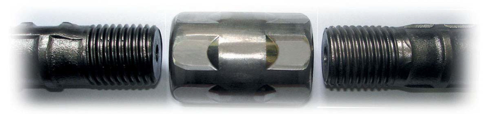
  •  We extend the bar thread at one side to allow the coupler to screw right on, flush with bar end. On assembly the bar ends are placed against each other and the coupler rotated onto the short thread to form the connection
  • Turn the coupler onto the short thread to complete the assembly and tighten the bar with a wrench


Used in applications of larger diameter, long bars. Where bars can be rotated but may be difficult to do so. E.g.: Over 6 metre long 32mm bars (and above) in a horizontal plane.

TYPE C

  • We extend the bar thread at one side to allow the lock-nut and coupler to screw right on flush with bar end
  • To assemble, the bar ends are placed against each other and the coupler rotated onto the short thread to form the connection. Wrench tighten the coupler onto the short bar and rotate the lock nut against the coupler and wrench tight


Used for construction of prefabricated cages, or fixing hooked/cranked bars.
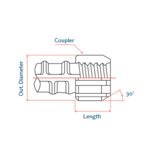
 

BS.4449
NOMINAL BAR SIZE (Ømm) 12 16 20 25(26) 32 40 50
COUPLER DIAMETER (mm) 19 23 31 38 48 60 75
HEXAGON-B (mm) 17 21 29 36 46 56 70
COUPLER LENGTH 30 38 46 58 70 86 110


ASTM A615/A 615M
BAR DESIGNATION (#) 3(10) 4(13) 5(16) 6(19) 7(22) 8(25) 9(29) 10(32) 11(36) 14(43) 18(57)
COUPLER DIAMETER (mm) 18 20 24 28 32 38 42 48 55 65 85
COUPLER LENGTH 22 30 38 45 50 58 65 70 78 95 125

Weldable couplers allow unrestricted and easy placing of re-bar to steel piles, forms, etc.

Coupler has an attached nail plate for accurate and easy fixing to wooden form.

BS.4449
BAR SIZE 12 16 20 25 28 32 40 50
COUPLER DIAMETER (mm) 19 23 31 38 43 48 60 75
COUPLER LENGTH 30 38 46 58 65 70 86 110


ASTM A615/A 615M
BAR DESIGNATION (#) 3(10) 4(13) 5(16) 6(19) 7(22) 8(25) 9(29) 10(32) 11(36) 14(43) 18(57)
COUPLER DIAMETER (mm) 18 20 24 28 32 38 42 48 55 65 85
COUPLER LENGTH 22 30 38 45 50 58 65 70 78 95 125

LONGITUDINAL RE-BARS

SHEAR RE-BARS

BS 4449
BAR SIZE 12 16 20 25 28 32 40 50
LONGITUDINAL RE-BARS DIAMETER 29 36 45 56 65 72 90 112
THICKNESS 6 7 8 9 10 10 18 20
H 15 19 23 29 32 35 43 55
SHEER RE-BARS DIAMETER 32 51 64 80 89 102 127 159
THICKNESS 8 8 10 14 16 18 22 26
LOCK NUT WIDTH -8 10 13 18 -18 18 25 -30